Switches are present in almost any kind of electronic circuit, from effect pedals to cellphones. And even if many times we’re not aware of that they are essential, as they’re the main way we have to interact with electronic devices. Do you want to learn more about the different switches and how they’re used in electronic circuits? Then keep reading!
Getting Started
A switch is any electrical component that can cut and restore an electronic path, and thus breaking or letting the current flow through it. As we can’t modify the electronic circuit directly, our only way to communicate with it is controlling its switches. That way, we can select different clipping diodes with a toggle switch or engage an effect pedal through a footswitch, write in our computer through our keyboard’s mechanical switches or tap in our phone’s capacitive screen. Switches can be sorted according to different factors:
A- How they are operated
Depending on how the switch is engaged or disengaged, we have different groups. These are the two more relevant regarding audio and effect pedal circuits:
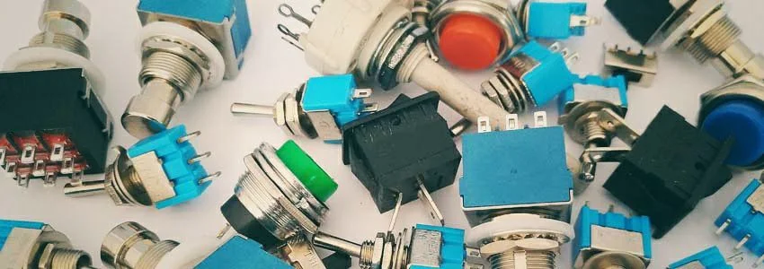
- Mechanical switches: these are the most common and familiar switches and they are operated manually, as a light button or your computer power on switch. In your effect pedals you’ve come across some of them: Footswitches, Toggle Switches, DPDTs, dip switches… As these are the main switches you’ll be using with your effect pedals, we’ll explain them in detail after.
- Electronic switches are more complex than mechanical switches, and use different kinds of electric circuits to cut or allow the current flow. You probably already know one of these systems: the buffered bypass we can find in many pedals (like Boss) that, instead of a True Bypass footswitch, uses an arrangement of transistors to send the instrument sound through the effect circuit or directly to the output.
Another electronic switch widely used is the relay. In standard relays, a coil and a small magnet are used to control the current flow. Other common electronic switches are capacitive switches and light switches. There’s also more switch families, as temperature switches to control the temperature of an oven, mercury switches to open or close an electronic circuit depending on the tilt…
B- How the actuator works
Mechanical switches can also be classified depending on how the the force is applied to them. These are the ones you’ll find in our diy effect pedal kits:
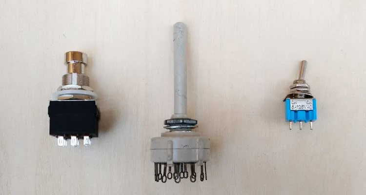
- Toggle switches use a two part joint: a lever, which is moved through different positions in a plane (usually two or three) and a contact that connects the different pins depending on the position.
- Rotary switches are operated through a twisting motion to connect the different pads.
- Footswitches, where the force is operated perpendicularly to them with the foot and usually have two positions.
C- The arrangement of the output pins
For each kind of switch, you will find a nomenclature for its pins that will let you know how they are disposed. This is quite useful as, when they have many pins, how a switch will behave may not be very intuitive. The code will have the format xPyT, where x and y are numbers:
- P refers to the number of Poles of the switch, what means how many circuits the switch is controlling. 1P (or SP) only control 1 circuit, 2P (or DP) control 2 circuits (and acts as if two identical SP switches were glued together), 3P control 3 circuits (like three SP switches linked together) and so on.
- T refers to the number of Throws each pole has. The easier way to visualize it is to imagine that each pole is catching the incoming electric flow, and then is able to let it go through any of its throws. An 1T (or ST) switch will only be able to throw it through 1 pin, a 2T (or DT) switch will be able to throw it through 2 different pins and so on.
The simplest switch is a SPST, which is the standard on/off switch: one position allows the current to flow and the other one cuts it.
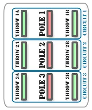
In this picture are illustrated the poles and throws in a 3PDT footswitch. It has three poles (3P), or in other words, three internal switching circuits. It has two throws (DT), which means that each pole can send the signal through two different pins.
D- Latching or non-latching
The last classification we’ll use is whether the switch is latching or non-latching. A latching switch will, once operated, keep its state until it is operated again. A non-latching switch, on the other side, will return to its original position once it is released. The 3PDT footswitch and the toggle switches you will use in your effect pedal projects are latching. Let’s consider the 3PDT: once you hit it to engage your distortion pedal, the effect stays on until you hit it again. If you were using a non-latching 3PDT, the distortion would only be on as long as you kept the footswitch pushed. The simplest form of non-latching switch is the button, as the keys in your keyboard or the buttons of a vending machine. You can find as well SPDTs, DPDTs, 3PDTs and any other switch form as non-latching, but when building effect pedal kits you’ll almost always find latching switches.
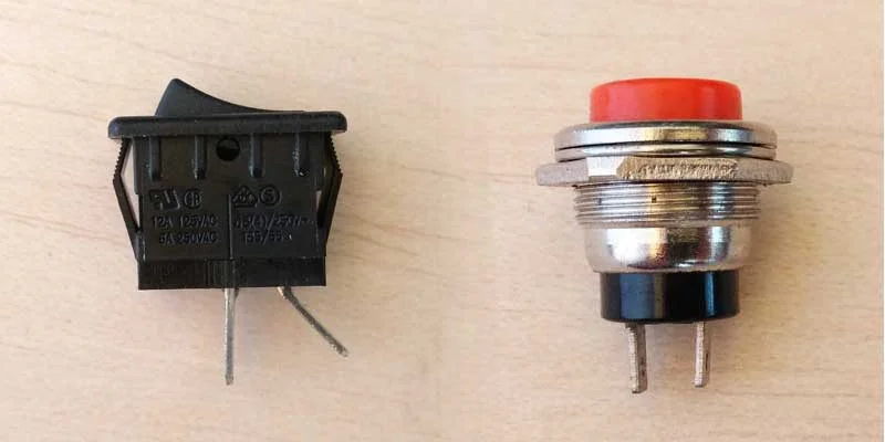
In this picture, if both switches were used as a power control, the latching one (left) would allow the current flow until it was set to the off position, and would remain there until it was set to the on position again. The button, on the other side, would only allow the current to flow when pressed. But as soon as it was released, would return to its original position and cut the power.
Effect Pedal Switches
In this section we’ll cover the most used switches in effect pedals. In every case, we’ve used red for the poles and green for the throws to make it easier to understand. Let’s start!
1- Toggle Switch SPDT ON-ON
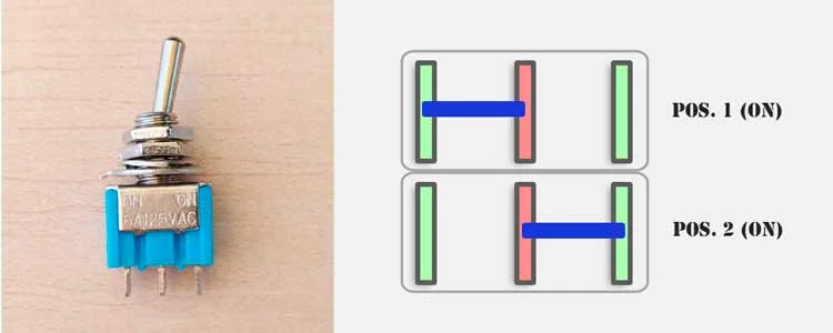
The toggle switch is widely used in effect pedals. The pole is the middle pin, and the throws are the left and right ones. Its basic usage is to select between two paths for your input signal. It has two positions: the lever can be either left or right, and the pole will be connected to one throw or the other alternatively. For example, it allows you to choose between two capacitors in a low pass filter to set the amount of highs in your tone.
2- Toggle Switch SPDT ON-OFF-ON
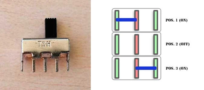
This version of toggle switch is not as common in effect pedals as the previous one, but is also used. You can also find it with the same lever system as the previous, and instead of having only two positions (left and right), it also has one middle position where the pole is not connected to any of the throws. Using the previous example, this switch would let you choose between two capacitors to filter your tone or no capacitor at all to avoid any kind of filtering.
3- DPDT Switch
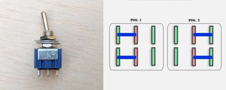
DPDT Toggle Switch: picture and internal schematic[/caption] The DPDT switch has two poles and two throws for each one. It works exactly as the SPDT switch, but it has two internal switching circuits. With this kind of switch we could select one of two capacitors for each pole, for example if our effect pedal has two gain stages and we want to do a filtering in each one.
4- 3PDT Footswitch
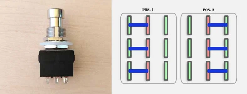
One of the most used switches in effect pedals and diy projects, as almost every pedal will need at least one of them! This switch, also known as stompswitch, has three poles and two throws for each one. It has two positions: the poles are alternatively connected to the throw on its left (position 1) or on its right (position 2). Keep in mind that the poles are synchronized: they are all in position 1 or in position 2. You can’t have a pole connected to the throw on its right and another one connected to the throw on its left. The standard usage of this switch is to provide the effect pedal with True Bypass switching system, where the internal circuitry of the pedal is completely isolated once the pedal is disengaged to avoid any tone loss, a common problem with buffered bypass.
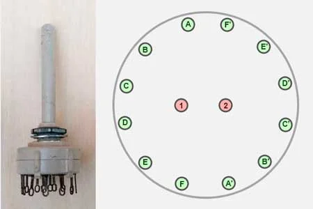
5- Rotary Switch
The last switch we’ll cover here is the rotary switch. It is more complex than the previous one as each pole usually has many throws as in the next picture: a 2P6T. This means that each pole can route the signal through 6 different paths. These switches are used when a wide variety of options is needed. Following the example we’ve used before, we could have 6 different filtering options available for each one of the poles.
We hope this post has clarified a bit the internal characteristics of switches and that from now on you understand a bit better how they work when building your own effect pedal kits or electronic projects!