Delay pedals are widely used, but what are they exactly and how do they work? In this first post, we’ll go back in time to find the origin of delay pedals and the basic concepts behind them. In the next post we’ll give you some tips and tricks you can achieve with them.
1 – Early days: the tape echo.
Nowadays we have a wide variety of digital delay pedals, but the first delays were based around a magnetic tape loops in magnetic recording systems, also known as tape echo. Audio engineers started experimenting with them in the early 40s as magnetic tape started becoming the main choice for recording. While it’s not sure, there are many who say that Les Paul was the originator of the tape echo, or at least that he had a great influence in the development of this effect. Many tape delay systems started appearing in the next years, and in the 50s they were commercially available (to the ones that could afford them!). The best know are probably the Roland Space Echo and the Echoplex.
While some of them were authentic engineering pieces of art, the basic principle behind them was quite similar. The sound to be echoed was recorded in a loop of tape that was then passed through multiple heads that played back the original sound. To set the delay time, one could set the speed of the motor driving the tape loop or change the distance between heads. In some advanced systems the loop was fed back into the record head, allowing for multiple repetitions. There was another popular echo that used a magnetic drum instead of a tape loop that featured a quite longer life time over tapes. The main disadvantage of tape delays is that they required a high amount of precision and maintenance: tapes were to be replaced regularly, motors checked… Besides, the devices were quite large and the loop delay was limited by how slow the motors could run before the sound was too much degraded. All these factors made tape echos making them relatively unreliable. That’s when a new IC made its appearance to change delays forever: the Bucket Bridge Device (BBD).
2 – Analog delays: the Bucket Bridge Device (BBD)
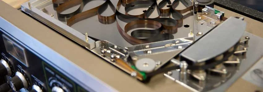
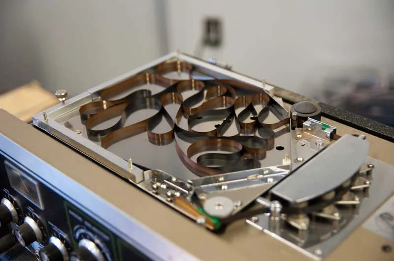
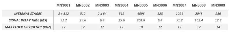
As their name suggests, Bucket Bridge Devices (BBD) consist of a high number of internal stages that act as small switches. The IC is fed with a clock line and the input signal, and with each clock tick the signal goes from one stage to the next until it reaches the output of the IC. The total amount of delay depends on the number of stages and the clock frequency and is usually between a few milliseconds and a few hundreds of milliseconds. Some advanced techniques allowed to get more delay time without degrading too much the signal.
The first obvious advantage was their reduced size. While tape echo devices needed electric motors and a physical tape loop that could be quite large, BBD analog delays were 100% electronic. As they didn’t need any mechanical element and just consisted on an electronic PCB their size was way smaller, making them easier to manipulate or to bring to a gig. The second advantage was the fact that they were pure electronic devices, making them a lot more reliable than tape echos as they didn’t had mechanical parts that could break or malfunction. As to how they work, in BBD based delays the signal is initially splitted in two paths. The first one goes straight to the output without any modification: this is the dry signal path. The second one is routed through to the Bucket Bridge Device, which is in charge of delaying it. After the signal is processed, it is mixed back together with the dry signal.
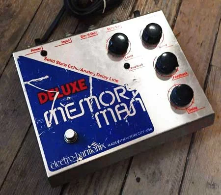
Many of the BBD analog delays appeared in the 70s, being a good alternative to tape echo. One of the most populars was the Electro-Harmonix Memory Man: featuring the MN3005 IC, this effect pedal delivered up to 320ms of delay. While they had a huge popularity over tape echos, analog delays still had some issues. In one hand, because of the limited number of stages in a BBD IC (4096 in the MN3005), these effects usually had shorter delay times. On the other, while passing from one stage to the other the signal suffered some degradation.
3 – Digital delays
When digital processing technology became available in the late 70s and 80s delays changed forever. At the beginning these units were only available as racks, but as electronics became smaller more and more pedals made their appearance in the market. Unlike in BBD delays, Analog to digital converters (ADCs) available in digital effects were able to perfectly sample the input signal with no sound degradation. This translated into huge delay times and clean sound reproduction. Early digital delays also had their issues: many of them used cheap and affordable 8 bit samplers that producing a harsher and colder sound than BBD. But with the quick development in digital processing and the price reduction of dedicated audio ICs, these issues became practically non-existent: nowadays, digital technology has advanced so much that it’s even possible to emulate digitally tape echos or BBD analog delays.
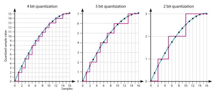
To understand how a digital delay works you just have to see it as a small recorder, that constantly makes a small recording of your playing. Then, this recorded signal can be delayed at wish, repeated as many times as desired and even modify the volume of the repetitions. But our signal is time-continous, meaning that there’s no abrupt jumps between one value and the next one and each two values are connected by an infinite number of values in between them. When we sample our sound it becomes an amount of disconnected points: this is our digital signal. The number of bits in the ADC dictates how many “levels” the sampler can pick from, just like if it was a collection of values. For example, When the ADC samples the signal, it will pick the digital value that is nearer from the analog signal value. This is know as quantization. For example, let’s assume our ADC has the following available values: 1, 2, 3…9 and10. If the input signal has a value of 7.3 the ADC will pick 7 because it is the nearer value from the ones it can pick from. On each sampling step there’s a small error, known as quantization error. This has an obvious conclusion: the more bits an ADC has, the more levels it can choose from and the more alike will be the digital and the analog original signals. For example, in an 8-bit sampler you have 2^8 = 256 levels, while in modern 24 bits ADCs you have 2^24=16777216 levels! In the previous example, our analog sound signal would be the blue line and the digital sampled signal the red line. As the number of bits increase, the red line becomes more and more similar to the blue line. With enough bits, we can assume both are the same.
Check out our Deep Blue Delay Kit and build your own PT2399 delay pedal!
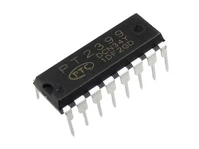
One of the best known delay ICs is the PT2399, and it is widely used in many delay and echo effect pedals. This dedicated audio IC has a low distortion (typically THD < 0.5%) and allows delay times of up to ~350ms (if longer delay times are set noise starts becoming an issue). These kind of dedicated audio ICs allow a lot of versatilty as all the sampling, delaying and DAC conversion is done inside this small circuit. Add a few external passive parts and you’ll have a basic delay effect pedal!
We hope you found this first issue interesting! In our next post we’ll explain the different delay parameters, as delay time or feedback, and give you some tips to get the most out of your delay pedal.