In our last post we made an introduction to switches, but with no real application circuits. In this next issue, we will present some electronic circuits you can build with switches and explain how you can use them with your gear. Some of them are a simple RC filter with a frequency selector and a 3PDT True Bypass switching system. Let’s get started!
ON/OFF filtered supply
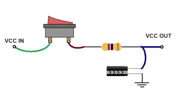
The first of the circuits we want to introduce is a ON/OFF filtered power supply. It only uses a simple SPST switch (if you need to review how switch names work don’t miss this post!). It can be either open (no current will flow through it and the power will be off) or closed (the current will flow through the switch and will be filtered by the resistor + capacitor).
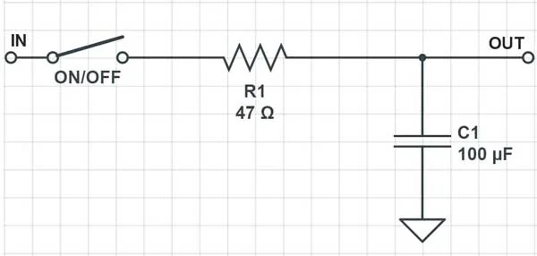
This is a good addition to add not only to effect pedals but to any electronic project that needs power (that is to say, almost all of them!), and provides an easy way to shut down the power when they’re not being used. The RC filter provides a cutoff frequency of ~30Hz that will stabilize the voltage and eliminate most of the high frequency noises that can be generated in your circuit. The resistor is fairly small to avoid loading the circuit and thus a big voltage drop. The bigger the capacitor the better, as the supply will be more stable. But be aware of using a capacitor with a higher voltage rating than your supply! Here’s how this circuit would look like:
SPDT filter selector
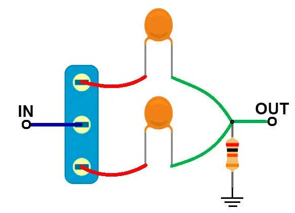
The next circuit is a simple RC high pass filter with a selector for the cut frequency. This simple circuit can be used independently and without power as it only has passive elements. You’ll find it useful if you want to modify the tone because you find your sound has too much bass, and can be placed anywhere in between your chain. Here’s the schematic:
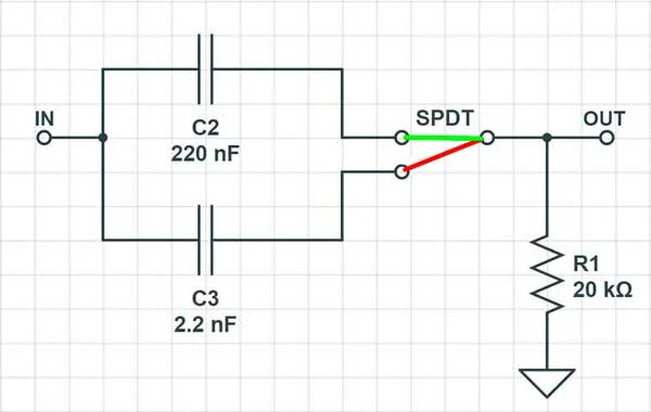
With the switch in the first position (green), the current flows through the C2 capacitor and the C3 capacitor is disconnected, getting a cutoff frequency of ~36Hz along with the 20k resistor, a very low frequency considering that the hearing range is within 20Hz and 20kHz, so the sound will go through with just a slight reduction of bass. If you need the sound not to be modified at all, you can use higher capacitor values (4.7uF will give you a cutoff frequency of ~1.6Hz, just enough to block any DC but letting all of your signal pass through). In the second position (red) only C3 will be active, and we’ll have an RC filter with a cutoff frequency of ~3.6kHz. In this case, your tone will drop almost all of the bass and you’ll make more noticeable the mids and highs. You can modify the capacitor value the same way as before, considering that higher capacitor values will translate into a lower cutoff frequency (and hence more bass). Here’s how this circuit would look like with electronic parts:
3PDT True Bypass switching system
The last application circuit we’ll cover is one you will find in all of our kits: the 3PDT True Bypass switching system. In this circuit, a 3PDT footswitch is used to completely isolate the circuit of the pedal when you are not using it to avoid tone loss as it happens with buffered bypass pedals. Besides, a led shows whether the pedal is on or off. There are multiple ways of wiring to achieve different results; here’s the most straightforward one:
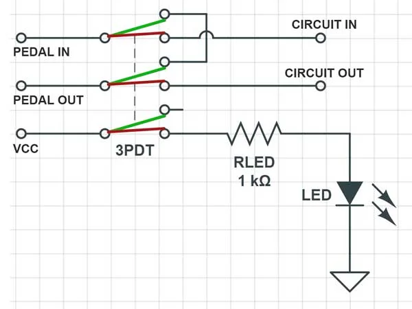
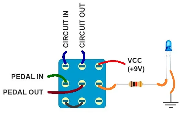
Pedal in/out represent the input/output of the pedal(the box, no the circuitry) while circuit in/out are the send/return to the effect pedal board. The easiest way to visualize how a circuit with switches work is to remember that, at one given time, they are all in the same position (either green or red). With that in mind, you just have to follow the path of the signal for any given input. First of all, let’s consider the green position. Your instrument’s signal comes from the “Pedal In” pin, then goes through the 3PDT and returns directly to the “Pedal Out” pin. This way, you are achieving a True Bypass switching: circuit in/out are no phisically connected to the sound path, so they won’t affect to your tone. The led resistor is not connected to anything, so the led will be off. When you hit the footswitch, it goes to the red position. Now, “Pedal In” is directly connected to “Circuit In“. The signal goes to the effect pedal PCB, is modified (for example, to achieve an overdrive sound) and returns to the “Circuit Out” pin, which is directly connected to the “Pedal Out”. Besides, the led resistor will be connected to the power supply (VCC), so the led will be on. This is how your 3PDT wiring will look like:
We hope you find these applications with switches practical, now you’re ready to build your own effect pedal kits and design your own switching circuits. Until next time, stay musical!